Lessons from my first useful Zoo Modeling App print
I finally sat down in front of Zoo Modeling App as a proper user last night, after mostly writing code and designing features for it for the last year along with my colleagues at Zoo. I have designed a few parts from scratch on the app before, but this is the first time I've had an idea for something I needed to model and print where I actually thought, "hey, I think our app could be a fun way to do this".
Success
I'm happy to report that I was successful in my task.

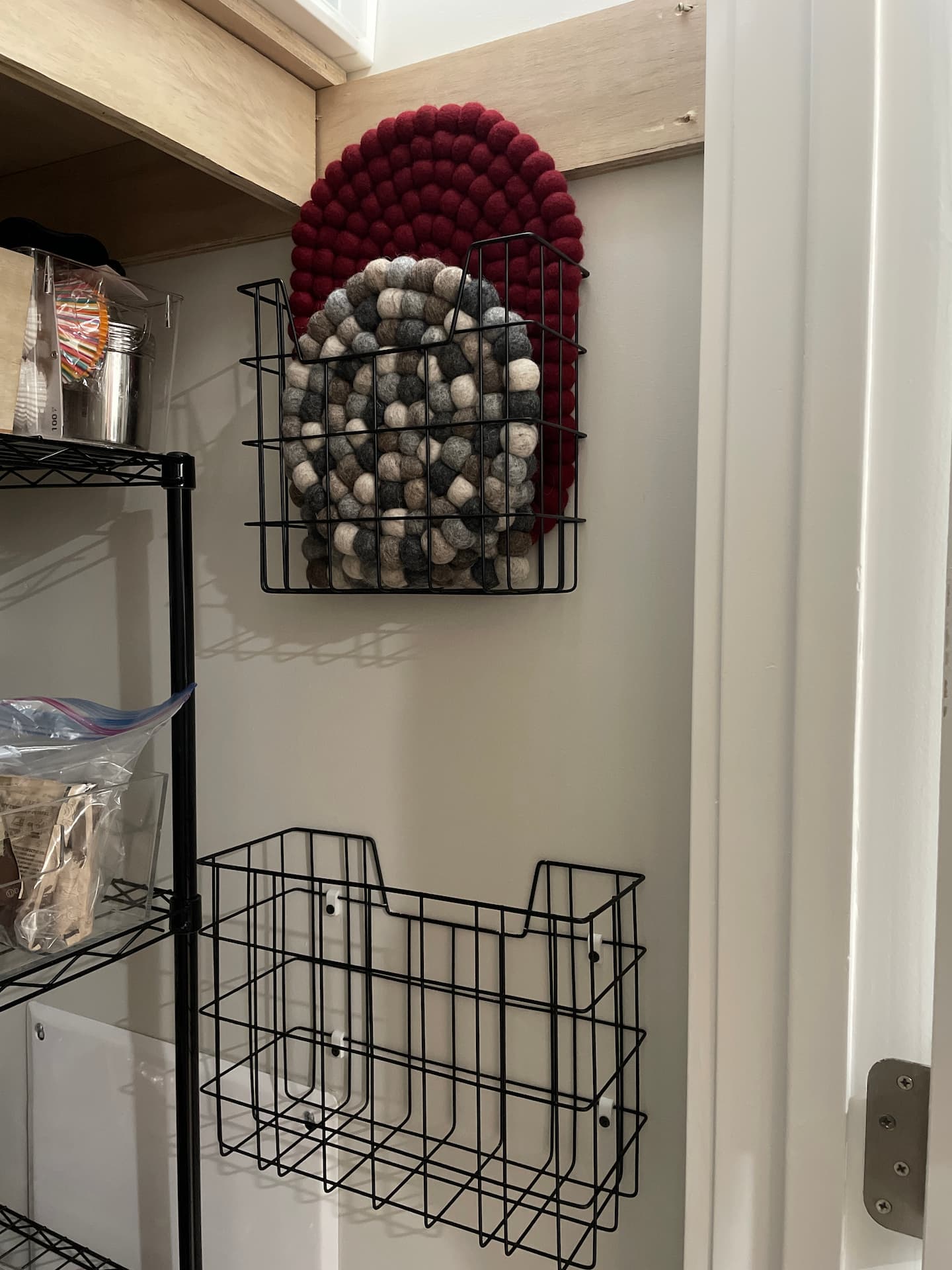
I made a set of clips that take a screw and press around the wire in these baskets, yay!
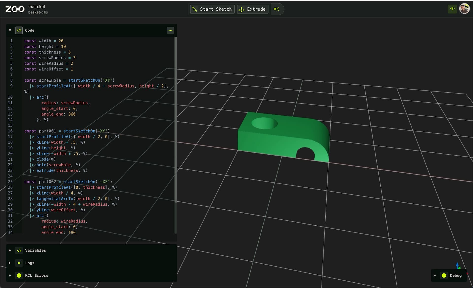
Here's what it looked like completed in Modeling App:

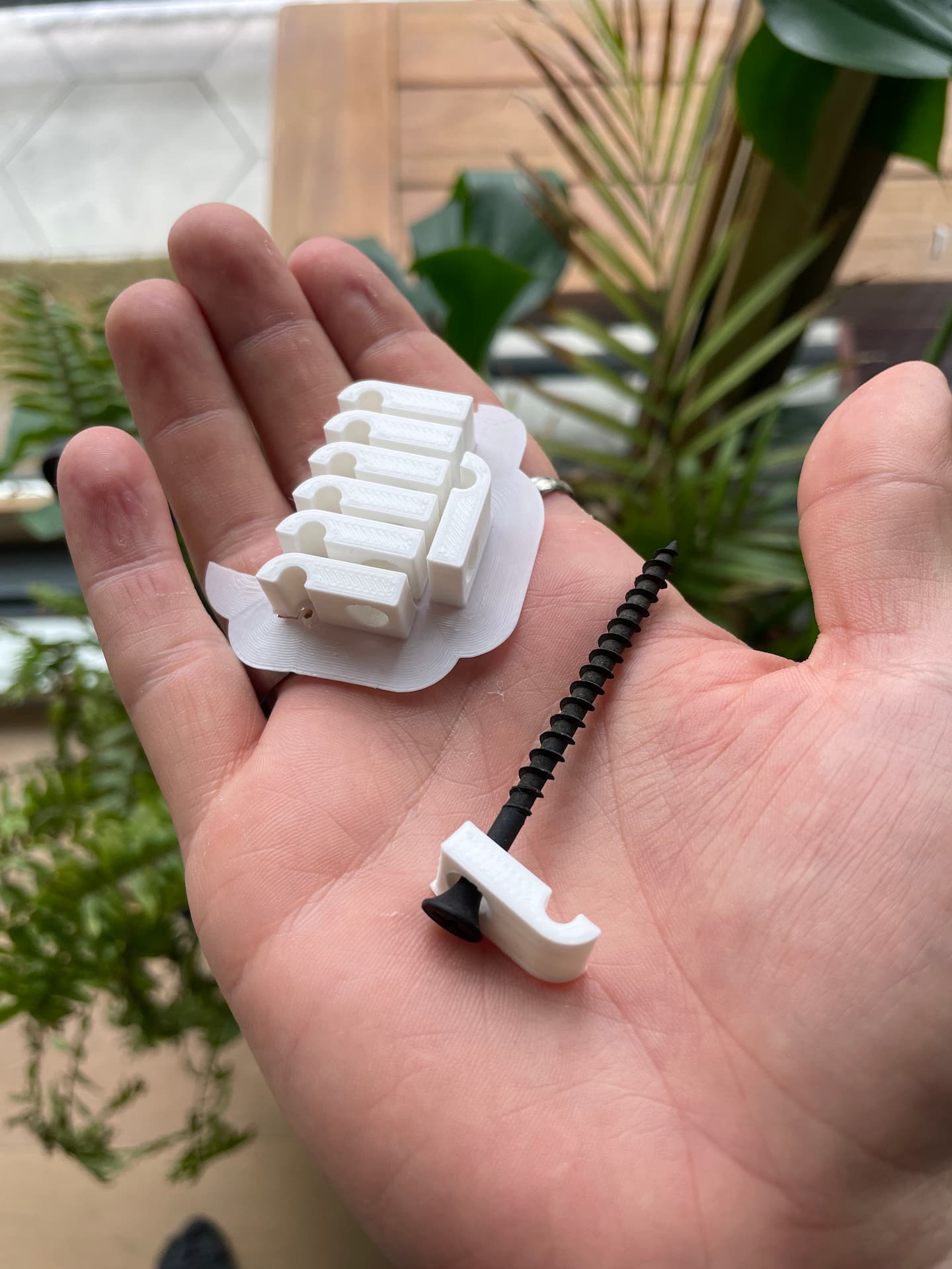
And here's what they looked like printed in my hands. It took me a round of iteration to get the fit right.

Rough Edges
Here are my rough notes on the rough edges I experienced while creating these:
- No cuts in two different planes
- This is a feature we're still building towards because cutting the same body from multiple planes is one of those incredibly hard spatial problems to bring to a new GPU-based architecture. Luckily as an insider I know a hack, that my slicer will merge separate bodies into one. So I made a part for the screw hole block and a part for the wire cut part. Being able to use variables actually made keeping this two parts "in sync" effortless though.
- Text editing is slooooow
- I think I've identified a memory leak in our text editor that is causing it to bog way down in certain editing scenarios. The UI and engine would be firing away just fine but something about the text editor would slow to a crawl when editing sketches with a lot of variable references (I think). I'll be opening an issue next week and investigating it.
- No rectangle command
- An easy convenience button/command we can make around the Line tool. We still feel pretty adamant that every sketch entity in Zoo Modeling App needs to be separately taggable, but there's nothing stopping us for writing the line values for you.
- No easy way to force lines to horizontal and vertical while point-and-clicking
- This isn't too crazy, we've discussed how we need to honor things like the
Shiftkey for this
- This isn't too crazy, we've discussed how we need to honor things like the
- No easy way to make point-and-click lines use existing variables for their values
- This forced me to hit against the slow text editing experience I was having. I would roughly place the lines in, then edit them to be horizontal and vertical, then edit all their values to be variables. We've discussed the need for a point-and-click Dimension-like tool and this is where that would fit in. The elegant thing is our Dimension tool will be able to just create new variables for you in your own code.
- Where was Export again?
- Having command searchable in the command bar would make finding the way to export a file much easier. Luckily Jess already made an issue for this a while back, and I think I've realized I can easily attach it to the
modelingMachine's commands.
- Having command searchable in the command bar would make finding the way to export a file much easier. Luckily Jess already made an issue for this a while back, and I think I've realized I can easily attach it to the
- I can delete the file extension and break my exported file
- This is a minor bug that we can resolve by re-adding the file extension after input is done and just not showing the file extension in the prompt window.
It's still easy to make brittle parts even with parametric design
This is the thing that I need to think hardest about with regard to UX. I was pretty responsible in setting up variables as I went along for the key dimensions of my part. However, I used those variables in such a way that changing one did not nudge everything else the way I had expected it to.
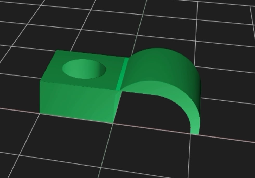
Here is what it looks like if I increase the wireRadius value from 2 to 6:

Because my call to tangentialArcTo and the value of thickness don't seem to account for the wire's diameter, I don't get an output that I would like to get back when adjusting a parameter, and instead the inner arch of the wire's through-cut ends up outside of the edge meant to be the outer profile.
How, as a software designer, do I help the user out of this situation, when they already have so much constraint and logic built into their part's code? I feel confident we can find solutions for this, but it is a non-trivial refactoring problem. Or a UX problem to guide users down a path of authoring parts that prevents them from getting into this situation in the first place.
Conclusion
This was a fun Saturday morning project to get me back in front of the tools I help build with fresh eyes. I see a lot of potential for polishing these rough edges with UX solutions in the near future, and I hope you'll reach out to us or open an issue if you think there is more for us to see!